TM-9-2815-220-24 - Page 321 of 1563
TM 9-2815-220-24
LOW VOLTAGE STARTER PROTECTION MODULE REPLACEMENT
0050 00
WP 0050 00-1
THIS WORK PACKAGE COVERS:
Removal and Installation
INITIAL SETUP:
Tools:
General mechanic’s tool kit (item 121, WP 0176)
Mandatory Replacement Parts:
Self locking nut (4) (item 37, WP 0175)
Personnel Required:
Track Vehicle Repairer (1) 63H10
Equipment Conditions:
Engine removed from vehicle and placed on a
flat stationary surface
NOTE
Low voltage protection modules are located differently on early model
engines as opposed to later model engines.
The module will either be
mounted on the crankcase next to the starter (early engine models) or
on the top deck, left side, front access panel (later engine models).
Removal and installation procedures are identical regardless of
location except for the ground lead on later engine model installations.
REMOVAL
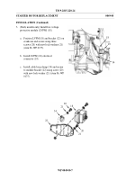
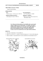
1. Disconnect wiring harness (1) from module (2).
2.
Remove two cap screws (3), washers (4) and self-locking nuts (5).
Discard self locking nuts.
3.
Remove module (2) (and ground lead (6) on later installations) from mounting bracket (7).
Early Installations (side of crankcase)
Later Installations (top mount)
1
6
2
3,4,5
7
2
1
Back to Top

