MWO-9-2320-272-20-4 - Page 5 of 20
MWO 9-2320-272-20-4
b. Automatic Throttle Kit Preparation.
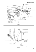
(1) Install two 12256573 bushings and 12368325 throttle lever assembly on 12255965-2 bellcrank
link assembly as shown in figure 6.
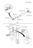
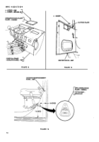
(2) Apply 12302758 pipe sealant to threads of 6-2 120302BA elbow and install elbow
(6-2 120302BA) in port of 12356930 air cylinder as shown in figure 7.
(3) Install MS35691-6 jamnut and MS35812-2 clevis on air cylinder rod. Leave a 0.250-inch gap
between jamnut (MS35691-6) and air cylinder (12356930) as shown in figure 7. Tighten jam nut
against clevis 10 Ib-ft (14 NŽm).
c. Automatic Throttle Kit Installation.
(1)
(2)
(3)
(4)
(5)
(6)
(7)
(8)
(9)
(10)
(11)
(12)
Position accelerator pedal pushrod on bellcrank Iink/throttle lever assembly and install
bellcrank link/throttle lever assembly on throttle bracket with throttle shaft, washer, and
MS24665-283 cotter pin as shown in figure 8.
Install accelerator pedal pushrod on bellcrank link/throttle lever assembly with washer
and MS24665-132 cotter pin as shown in figure 8.
Install ball joint, return spring, and throttle cable on bellcrank link assembly (12255965-2)
(TM 9-2320-272-20).
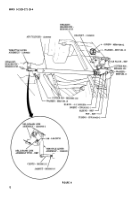
Install 12356928 bracket on cab floor with four MS27183-10 washers and MS90728-5L screws
as shown in figure 9.
Install air cylinder (12356930) on bracket (12356928) with MS20392-3C25 straight-headed pin,
MS27183-10 washer, and MS24665-132 cotter pin as shown in figure 9.
Install clevis (MS35812-2) on throttle lever assembly (12368325) with MS20392-3C25 straight-
headed pin, MS27183-10 washer, and MS24665-132 cotter pin as shown in figure 9.
Measure clearance between stud of bellcrank link assembly (12255965-2) and throttle lever
assembly (12368325). Clearance should be 0.06-0.08-inch as shown in figure 9.
NOTE
Perform steps 8 through 11 if clearance is not within
limits.
Remove cotter pin (MS24665-132), washer (MS27183-10), straight-headed pin
(MS20392-3C25), and clevis (MS35812-2) from throttle lever assembly (12368325) as
shown in figure 9.
Loosen jamnut (MS35691-6) and turn clevis (MS35812-2) to obtain proper clearance as
shown in figure 9.
Install clevis (MS35812-2) on throttle lever assembly (12368325) with straight-headed pin
(MS20392-3C25), washer (MS27183-10), and cotter pin (MS24665-132). Check clearance as
shown in figure 9.
Repeat steps 8 through 10 until proper clearance is obtained.
Install CPR102321-1 insert, sleeve, and CPR104420-2 tubing on elbow (6-2 120302BA) on air
cylinder (12356930) with nut as shown in figure 9.
5
Back to Top

