MWO-9-2320-272-24-1 - Page 13 of 25
MWO 9-2320-272-24-1
APPENDIX B
INSTALLATION INSTRUCTIONS AND ILLUSTRATIONS USED TO INSTALL SPRING BRAKE VALVE
GUARD KIT.
B-1 . VEHICLE PREPARATION.
a. Chock wheels. (Refer to TM 9-2320-272-10.)
b. Drain air tanks. (Refer to TM 9-2320-272-10.)
c. Release tension from parking brake cable. (Refer to TM 9-2320-272-20.)
d. Remove driver’s seat assembly. (Refer to TM 9-2320-272-20.)
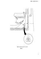
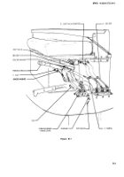
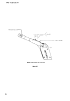
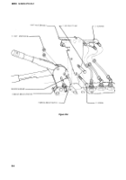
e. Tag air lines “a,” ‘%,” and “c,” and remove them from limit valve adapters as shown in figure B-1.
f. Remove parking brake lever and existing hardware as shown in figure B-L
NOTE
Refer to TM 9-237 for metal preparation and welding instructions.
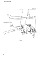
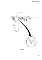
g. Position 12375363 plate to parking brake lever and secure with braze grade B, type optional, spec
MIL-B-7883 or weld class 1, spec MIL-STD-1261 as shown in figure B-2.
NOTE
Prime and paint parking brake lever in accordance with TM 43-0139.
B-2. KIT PREPARATION.
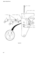
a. Remove adapters “b,“ "a,” and “c” from existing limit valve assembly ports as shown in figure B-3.
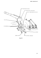
b. Coat male pipe threads with 12302758 sealant and install adapters in ports “c,” “a,” and ‘b” of
11669789-1 limit valve as shown in figure B-4.
c. Position limit valve assembly to 12375362 bracket and secure with two screws, washers, and
locknuts supplied with limit valve as shown in figure B-4. Tighten screws to 23-31 lb-in. (2.6-3.5 N•m).
B-3. KIT INSTALLATION.
a. Position parking brake cable clevis in parking brake housing and secure with pin, washer, and
MS24665-283 cotter pin as shown in figure B-5.
b. Install parking brake housing to parking brake handle bracket and secure with front screw and
MS51943-36 nut as shown in figure B-5.
c. Position parking brake switch and limit valve bracket to parking brake housing and secure with top
screw, spacer washer, and MS51943-36 nut as shown in figure B-6.
B-1
Back to Top

