MWO-9-2320-272-24-1 - Page 14 of 25
MWO 9-2320-272-24-1
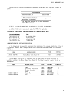
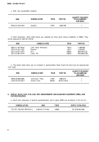
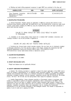
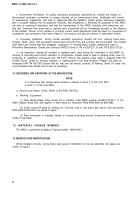
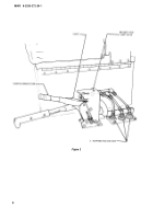
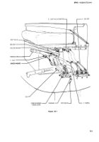
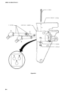
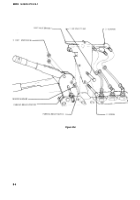
d. Secure parking brake housing with bottom screw and MS51943-36 nut as shown in figure B-6.
CAUTION
Ensure air lines are not twisted when installed.
e. Install air lines to limit valve adapters as shown in figure B-6.
NOTE
After completion of installation, perform functional test of parking brake
lever as follows:
Ensure limit valve toggle roller makes contact with plate on parking
brake handle when engaged.
Ensure limit valve roller arm does not touch limit valve mounting
bracket.
If interference occurs between limit valve roller arm and mounting
bracket, loosen mounting screws and adjust for clearance.
B-4. VEHICLE EQUIPMENT.
a.
b.
c.
Install driver’s seat assembly. (Refer to TM 9-2320-272-20.)
Adjust parking brake cable. (Refer to TM 9-2320-272-20.)
Perform the following fictional tests.
WARNING
NO ONE SHOULD BE IN FRONT OF VEHICLE DURING TESTING OF
BRAKES. FAILURE TO CLEAR AREA IN FRONT OF VEHICLE MAY
RESULT IN DEATH OR INJURY.
(1) Parking Brake. With engine at normal idle speed –
l Depress spring brake release control.
l Apply parking brake.
l Engage transmission in “1-5 drive.” (Vehicle should not move.)
(2) Spring Brake
. Apply service brakes.
l Apply parking brake.
. Engage transmission in “1-5 drive.”
. Increase engine speed to 1000 RPM.
l Slowly release service brakes. (Vehicle
(3) Air System Leakage.
air line fittings for leaks.
should not move.)
With air system at 130 psi and engine turned off, check newly installed
B-2
Back to Top

