TB-9-2320-279-13-1 - Page 351 of 524
TB 9-2320-279-13-1
0046-1
0046
AC WIRING HARNESS REPLACEMENT
DRAFT
-
-
-
-
-
-
-
-
-
-
-
-
-
-
-
-
-
-
-
-
-
-
-
-
-
-
-
-
-
-
-
-
-
-
-
-
-
REMOVAL
NOTE
•
Refer to Appendix A, Figure A-1, for electrical schematics.
•
Tag and mark connectors and wires prior to removal to ensure proper installation.
•
Remove cable ties as required.
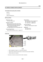
1. Remove six screws (1) and cover (2) from center console (3).
THIS WORK PACKAGE (WP) COVERS:
Removal
Installation
Follow-On Maintenance
INITIAL SETUP:
-
-
-
-
-
-
-
-
-
-
-
-
-
-
-
-
-
-
-
-
-
-
-
-
-
-
-
-
-
-
-
-
-
-
-
-
-
HEMAC087
Maintenance Level
Field Level Maintenance
Equipment Condition
Batteries disconnected (TM 9-2320-279-20).
Skid plate grille removed (TM 9-2320-279-20).
Engine cover open and engine side panel
removed (TM 9-2320-279-10).
AC heater/evaporator cover removed (WP 0037).
Tools and Special Tools
Tool Kit, General Mechanic’s (Item 7, Appendix F)
Materials/Parts
Tags, Identification (Item 9, Appendix E)
Ties, Cable (Item 11, Appendix E)
Ties, Cable (Item 12, Appendix E)
Personnel Required
MOS 52C, Utilities equipment repairer
References
TM 9-2320-279-10
TM 9-2320-279-20
Back to Top

