TB-9-2320-280-35-13 - Page 118 of 148
5-90
TB 9-2320-280-35-13
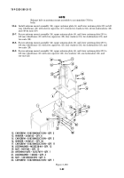
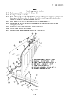
Figure 5-107.
17
18
5
3
16
15
6
7
8
9
10
11
12
13
13
14
~
~
~
FOUR-MAN VEHICLE
14
NOTE
Route SINCGARS antenna cable down B-beam with two man
configuration only.
29-2.
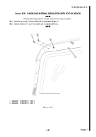
Route speaker cables (3) and (6) and SINCGARS antenna cable (19) down B-pillar (5) and secure
with three existing loop clamps (18) and capscrews (17).
29-3.
Route speaker power cable (3) to terminal board and secure with footman loop (8), loop clamp (9),
and existing capscrew (7).
29-4.
Route speaker R/T cable (6) and SINCGARS antenna cable (19) from overhead mount (20) along
cab enclosure panel (12) and secure with three existing loop clamps (10) and capscrews (11).
29-5.
Route speaker R/T cable (6) through tunnel (15) to HF 20 watt radio mount. Secure cable to
tunnel (15) with loop clamps (13) and capscrews (14).
29-6.
Route SINCGARS antenna cable (19) through cab enclosure panel (12) under tunnel insulation,
through integrated rack (16), to vicinity of SINCGARS mount.
Back to Top


