TB-9-2320-280-35-13 - Page 91 of 148
5-63
TB 9-2320-280-35-13
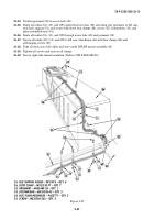
12. INC-EPUU CABLE – A3279383-3 – QTY. 1
15. EPLRS POWER CABLE – A3004939 – QTY. 1
18. URO EXTENSION CABLE – A3005328 – QTY. 1
20. SCREW – 9417875 – QTY. 4
21. LOCKWASHER – 131043 – QTY. 4
22. NUT 116002 – QTY. 4
Figure 5-83.
12
13
14
15
16
17
18
19
18
20
21
22
17
16
~
~
TUNNEL
INSULATION
NOTE
• Loosen left-side tunnel insulation before performing steps 21-6
through 21-8. (Refer to TM 9-2320-280-20.)
• SINCGARS model AN/VRC-92F shown.
• Previously routed cables are not shown for clarity.
21-6.
Route INC-EPUU cable (12) from integrated rack (14) down through center access hole (13) and
under left-side tunnel insulation (19) towards rear of vehicle.
21-7.
Route power cable (15) forward and under integrated rack (14) and under left-side tunnel
insulation (19) towards rear of vehicle.
21-8.
Route URO extension cable (18) towards URO bracket (17) between loudspeakers (16) and connect
to URO bracket (17) with four screws (20), lockwashers (21), and nuts (22). Route remaining URO
extension cable (18) under left-side tunnel insulation (19) and towards rear of vehicle.
21-9.
Secure left-side tunnel insulation (19). (Refer to TM 9-2320-280-20.)
Back to Top


