TB-9-2320-280-35-14 - Page 122 of 148
5-100
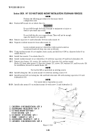
TB 9-2320-280-35-14
Section XXXV.
HF 150 WATT RADIO CABLES INSTALLATION (FOUR-MAN VEHICLES)
NOTE
Perform the following operations for four-man vehicle configuration
only.
35-1.
Route coupler control cable (11) and coupler P/A cable (2) along top of wheelhouse (14).
35-2.
Enlarge hole in antenna bracket (8) to 0.281-in. diameter.
35-3.
Secure cables (11) and (2) to wheelhouse (14) with clamp (10), existing screw (9), washer (12)
and nut (13).
35-4.
Route coupler control cable (11), coupler P/A cable (2), and SINCGARS antenna cable (7) under
antenna bracket (8), down side of wheelhouse (14) and secure with existing clamps (6) and self-
tapping screws (4).
35-5.
Route coupler control cable (11) and coupler P/A cable (2) along cargo floor (18) to vicinity of HF 150
Watt radio mount (1).
35-6.
Route power cable (20) from HF 150 Watt radio mount (1) to tunnel (34).
35-7.
Route power cable (20) along tunnel (34) and secure with three existing clamps (33) and
self-tapping screws (32).
35-8.
Route power cable (20) through cab enclosure panel (31) to terminal boards.
35-9.
Locate, mark, and drill three 0.147-in. diameter holes (36) in B-pillar (25).
35-10.
Secure speaker cables (23) and (3) to B-pillar (25) with three clamps (35) and self-tapping screws (4).
35-11.
Route speaker cables (23) and (3) down B-pillar (25). Secure with three loop clamps (26) and
existing capscrews (24).
35-12.
Route speaker cable (3) along cab enclosure panel (31). Secure with three clamps (29) and existing
capscrew (30).
35-13.
Route speaker cable (3) along tunnel (34) and secure with existing loop clamps (33) and
self-tapping screws (32).
35-14.
Route speaker cable (3) to vicinity of HF 150 Watt radio mount (1).
35-15.
Route speaker power cable (23) along B-beam (21) and behind seatback (22) to terminal boards.
Secure with loop clamp (29), existing footman loop (28), and existing capscrew (27).
35-16.
Drill two 0.147-in. diameter holes (16) in cargo floor (18).
35-17.
Secure coupler control cable (11), coupler P/A cable (2), and radio power cable (20) to cargo floor (18)
with loop clamp (17) and (19) and self-tapping screws (4).
35-18.
Route coupler P/A cable (2) to radio mount (1).
35-19.
Secure coupler control cable (11) and radio power cable (20). Route both cables (11) and (20) to radio
mount (1).
35-20.
Install chaff guard (5) in seatwell area (15) as required.
1
2
3
4
5
~
6
7
8
9
10
2
11
12
13
14
6
15
16
16
19
4
11
20
17
18
4
4
~
~
3.25
8.50
2.0
~
Figure 5-124.
Back to Top

