TB-9-2320-302-13-P-1 - Page 125 of 380
TB 9-2320-302-13&P-1
REAR ARMOR REPLACEMENT - CONTINUED
0023 00
0023 00-7/(0023 00-8 Blank)
INSTALLATION - CONTINUED
7.
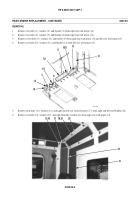
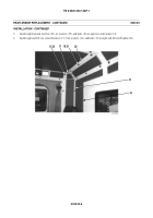
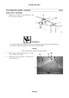
Install bracket (12), six washers (11), and bolts (10) on left rear wall armor (13).
8.
Install bracket (9), seven washers (8), and bolts (7) on right rear wall armor (14) and left rear wall armor (13).
9.
Install bracket (6), two washers (5), and bolts (4) on right rear wall armor (14).
10.
Install bracket (3), two washers (2), and bolts (1) on right rear wall armor (14).
11.
Install escape hatch (WP 0027 00).
12.
If equipped, install arctic heater box. For the M915A3P1, M916A3P1, and M917A2P1, refer to TM 9-2320-302-20-2.
For the M915A4P1, refer to TM 9-2320-303-24-1. For the M915A2P1, M916A1P1, M916A2P1, and M917A1P1, refer
to TM 9-2320-363-20-2.
13.
Install fire extinguisher bracket. For the M915A3P1, M916A3P1, and M917A2P1, refer to TM 9-2320-302-20-2. For
the M915A4P1, refer to TM 9-2320-303-24-1. For the M915A2P1, M916A1P1, M916A2P1, and M917A1P1, refer to
TM 9-2320-363-20-2.
14.
Install transmission shift tower. For the M915A3P1, M916A3P1, and M917A2P1, refer to TM 9-2320-302-20-2. For the
M915A4P1, refer to TM 9-2320-303-24-1. For the M915A2P1, M916A1P1, M916A2P1, and M917A1P1, refer to TM
9-2320-363-20-2.
15.
Install right and left seats. For the M915A3P1, M916A3P1, and M917A2P1, refer to TM 9-2320-302-20-2. For the
M915A4P1, refer to TM 9-2320-303-24-1. For the M915A2P1, M916A1P1, M916A2P1, and M917A1P1, refer to TM
9-2320-363-20-2.
END OF WORK PACKAGE
417-158
13
12
10,11
9
7,8
6
4,5
3
1,2
14
Back to Top


