TB-9-2320-302-13-P-1 - Page 197 of 380
Installation Manual – P/N 0257550622-00
(Doc No.:
II
113500-1 D)
Freightliner M915 / M916 -
Crew Protection Kit
Page 5 of 125
6. FASTENERS .
.........................................................................................................................
98
6.1 Definitions of Maximal Initial Torque.
....................................................................................
98
6.2 Fastener Maps.
.....................................................................................................................
99
7. M915-A2 and M916-A1 Specific Instructions.
...................................................................
108
7.1 Preparation Work for Cab Support Installation (M916-A1 only).
.........................................
108
7.2 Hood Spacer Installation (M915-A2 and M916-A1) .
...........................................................
112
7.3 Installation of the LH Wheel Housing (M915-A2 and M916-A1) .
........................................
113
7.4 Installation of the RH Wheel Housing (M915-A2 and M916-A1).
........................................
117
7.5 Shift Tower Installation (M916-A1 only).
.............................................................................
118
7.6 Shift Tower Installation (M915-A2 only).
.............................................................................
120
7.7 Rear Wall Mounting Plate (M915-A2 and M916-A1).
..........................................................
122
7.8 Relocate Engine Check Connector (M915-A2 and M916-A1) .
...........................................
124
List of Figures
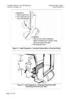
Figure 2-1. Cabin Preparations - Cutting the External Mirrors’ Electrical Wiring .
.......................
12
Figure 2-2. Cabin Preparations - Installing Cutting-Pattern #998 and
Drilling One 8-mm (5/16”) Hole .
.............................................................................
12
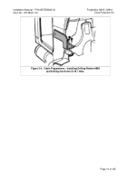
Figure 2-3. Cabin Preparations - Installing Cutting-Pattern #999 and
Drilling One 8-mm (5/16”) Hole .
.............................................................................
13
Figure 4-1. General View before Kit Installation .
........................................................................
22
Figure 4-2. General View after Kit Installation .
...........................................................................
22
Figure 5-1. Supplemental Cab Support Kit Installation – Final View after Assembly Completion23
Figure 5-2. Cab Support Reinforcement Kit Installation - Parts.
.................................................
23
Figure 5-3. Supplemental Cab Support Reinforcement Kit Installation – Rubber Bumper (#179)
Removal / Installation.
............................................................................................
25
Figure 5-4. Installing the RH Wheel Housing – Final View after Assembly Completion .
............
26
Figure 5-5. Installing the RH Wheel Housing - Parts .
.................................................................
26
Figure 5-6. Installing the RH Wheel Housing – Placing the RH Wheel Housing Support Arm .
.. 28
Figure 5-6a. Installing the RH Wheel Housing – RH Wheel Housing Fasteners .
.......................
29
Figure 5-7. Installing the LH Wheel Housing – Final View after Assembly Completion.
.............
30
Figure 5-8. Installing the LH Wheel Housing - Parts.
..................................................................
30
Figure 5-9. Installing the LH Wheel Housing – Placing the LH Wheel Housing Support Arm .
... 32
Figure 5-9a. Installing the LH Wheel Housing – LH Wheel Housing Fasteners .
........................
32
Figure 5-10. Floor Kit Installation - Final View .
...........................................................................
33
Figure 5-11. Floor Kit Installation – Parts.
...................................................................................
33
Figure 5-12. LH (Driver’s) Floor Kit Installation (1 of 4) .
.............................................................
34
Figure 5-13. RH (Passenger’s) Floor Kit Installation (2 of 4) .
.....................................................
34
Figure 5-14. Floor Kit Installation (3 of 4).
...................................................................................
35
Figure 5-15. Floor Kit Installation (4 of 4).
...................................................................................
35
Figure 5-16. RH Kit Installation - Final View .
..............................................................................
36
Figure 5-17. RH Kit Installation – Parts.
......................................................................................
36
Figure 5-18. RH Kit Installation (1 of 3).
......................................................................................
38
Figure 5-19. RH Kit Installation (2 of 3).
......................................................................................
38
Figure 5-20. RH Kit Installation (3 of 3).
......................................................................................
38
Figure 5-21. LH Kit Installation - Final View.
...............................................................................
39
Figure 5-22. LH Kit Installation – Parts .
......................................................................................
39
Figure 5-23. LH Kit Installation (1 of 3) .
......................................................................................
40
Figure 5-24. LH Kit Installation (2 of 3) .
......................................................................................
40
Figure 5-25. LH Kit Installation (3 of 3) .
......................................................................................
41
Figure 5-26. Backside Kit Installation - Final View.
.....................................................................
42
Back to Top


