TB-9-2320-302-13-P-1 - Page 200 of 380
Installation Manual – P/N 0257550622-00
(Doc No.:
II
113500-1 D)
Freightliner M915 / M916 -
Crew Protection Kit
Page 8 of 125
Figure 6-3. Fasteners Map - Floor and Firewall.
.......................................................................
101
Figure 6-4. Fasteners Map - RH and LH sides .
........................................................................
102
Figure 6-5. Fasteners Map – Backside.
....................................................................................
103
Figure 6-6. Fasteners Map – Roof.
...........................................................................................
104
Figure 6-7. Fasteners Map - Windscreen and Front Cover (1 of 2).
.........................................
105
Figure 6-8. Fasteners Map - Windscreen and Front Cover (2 of 2).
.........................................
106
Figure 6-9. Fasteners Map - RH and LH Doors.
.......................................................................
107
Figure 7-1. Elbow Adjustment.
..................................................................................................
110
Figure 7-2. Hose Wrap Location.
..............................................................................................
110
Figure 7-3. Hose Wrap Location.
..............................................................................................
111
Figure 7-4. Strap Installation.
....................................................................................................
111
Figure 7-5. Hood Spacer.
..........................................................................................................
112
Figure 7-6. #967 Installation .
....................................................................................................
114
Figure 7-7. Wheel Housing Support Arm.
.................................................................................
114
Figure 7-8. Wheel Housing .
......................................................................................................
116
Figure 7-9. Hose Wrap Location.
..............................................................................................
116
Figure 7-10. Shift Tower Installation (M915-A2) .
......................................................................
119
Figure 7-11. Shift Tower Installation (M916-A1) .
......................................................................
121
Figure 7-12. Mounting Plate Installation .
..................................................................................
123
Figure 7-13. Engine Check Bracket Install.
...............................................................................
124
List of Tables
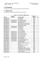
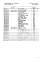
Table 3-1. Kit Inventory - Ballistic Items.
.....................................................................................
14
Table 3-2. Kit Inventory - Non-Ballistic Items.
.............................................................................
16
Table 3-3. Kit Inventory - Off-the-Shelf Items .
............................................................................
18
Table 3-4. Kit Inventory - M915-A2 and M916-A1 Adaptation Items (113502-1).
.......................
18
Table 3-5. Kit Inventory - Fasteners List.
....................................................................................
19
Table 4-1. Kit Installation Checklist.
............................................................................................
21
Table 6-1. Definitions of Maximal Initial Torque.
.........................................................................
98
Back to Top


