TB-9-2320-302-13-P-1 - Page 69 of 380
TB 9-2320-302-13&P-1
DOOR ASSEMBLY REPLACEMENT - CONTINUED
0012 00
0012 00-3
REMOVAL - CONTINUED
NOTE
Door assembly weighs 330 lb (150 kg).
3.
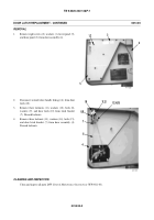
Install two lifting links on two weld bosses (10).
4.
Attach lifting device to two lifting links on door
assembly (13).
5.
Using lifting device, hold door suspended and remove
five bolts (11), washers (12), and door assembly (13)
from vehicle.
6.
Remove lifting device from door assembly (13).
7.
Remove two lifting links from two weld bosses (10).
CLEANING AND INSPECTION
Clean and inspect all parts IAW
General Maintenance Instructions
(WP 0011 00).
INSTALLATION
WARNING
Use extreme caution when handling heavy parts. Provide adequate support and use assistance during proce-
dure. Ensure that any lifting device used is in good condition and of suitable load capacity. Keep clear of
heavy parts supported only by lifting device. Failure to follow this warning may cause injury or death to per-
sonnel.
NOTE
Door assembly weighs 330 lb (150 kg).
1.
Attach two lifting links to two weld bosses (10).
2.
Attach lifting device to door assembly (13).
3.
Using lifting device, align holes in door assembly (13) with holes on side of cab and install five washers (12), bolts (11),
and door assembly (13) to vehicle.
4.
Check alignment between door assembly (13) and cab opening. Adjust door assembly as necessary until alignment is
correct.
5.
Remove two lifting links from two weld bosses (10).
417-271
10
11,12
13
Back to Top


