TB-9-2320-302-13-P-1 - Page 70 of 380
TB 9-2320-302-13&P-1
DOOR ASSEMBLY REPLACEMENT - CONTINUED
0012 00
0012 00-4
INSTALLATION - CONTINUED
6.
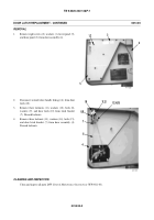
Install lower hinge (9), door detent (7) to lower hinge
assembly with four washers (6), bolts (5) and two
bolts (8).
7.
Install upper hinge (4), door bumper (3) to upper hinge
assembly with three washers (2) and bolts (1).
8.
Verify correct operation of door assembly.
9.
Check alignment of latch (WP 0016 00).
10.
If removed, install outside mirror on door assembly. For the M915A3P1, M916A3P1, and M917A2P1, refer to TM 9-
2320-302-20-2 series. For the M915A4P1, refer to TM 9-2320-303-24-1. For the M915A2P1, M916A1P1, M916A2P1,
and M917A1P1, refer to TM 9-2320-363-20-2.
END OF WORK PACKAGE
417-270
Back to Top


