TB-9-2320-302-13-P-3 - Page 122 of 240
TB 9-2320-302-13&P-3
EVAPORATOR ASSEMBLY MAINTENANCE - CONTINUED
0017 00
0017 00-14
ASSEMBLY - CONTINUED
NOTE
Tag wires and hoses to aid in installation.
6.
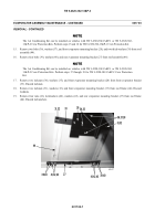
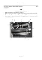
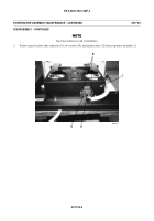
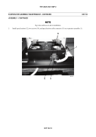
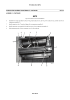
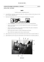
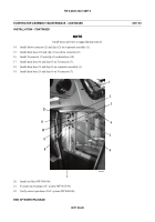
Install blower motor assembly (4), black wire ground connector (3), red wire power connector (2), and four nuts (6) on
evaporator assembly (1).
7.
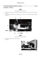
Install expansion valve (7) and two fittings (8) on evaporator assembly (1).
8.
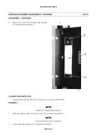
Install evaporator core assembly (10) and four screws (9) on evaporator assembly (1).
9.
Push thermostat probe (5) into evaporator core (10) fins as shown.
449-072
1
2
3
4
5
6
7
8
9
10
9
6
Back to Top

