TB-9-2320-335-13-P - Page 118 of 680
3-36
3-76.1. THERMOSTAT REPLACEMENT (SERIAL NUMBERS 300000 AND ABOVE)
This task covers:
a. Removal
b.
Installation
1.
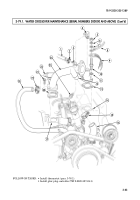
Remove capscrew (2), washer (3), wiring harness (4), and clamp (1) from bracket (5).
2.
Remove nut (7), lockwasher (6), and bracket (5) from stud (8). Discard lockwasher (6).
3.
Remove stud (8), capscrew (9), thermostat housing (10), gasket (11), and thermostat (12) from water
crossover (14). Discard gasket (11).
4.
Clean gasket surface on water crossover (14) and thermostat housing (10).
1.
Install thermostat (12) into water crossover (14), ensuring valve sensor (13) points toward water
crossover (14).
2.
Position gasket (11) on thermostat housing (10). Apply sealing compound to fastener threads and
insert capscrew (9) and stud (8) to align gasket (11).
3.
Install thermostat housing (10) over thermostat (12) and on water crossover (14) with capscrew (9)
and stud (8). Tighten capscrew (9) and stud (8) to 25 lb-ft (34 N
•
m).
4.
Install bracket (5) on stud (8) with lockwasher (6) and nut (7).
5.
Install clamp (1) and wiring harness (4) on bracket (5) with washer (3) and capscrew (2).
b. Installation
a. Removal
TB 9-2320-335-13&P
INITIAL SETUP:
Tools
General mechanic’s tool kit:
automotive (Appendix B, Item 1)
Maintenance and repair shop equipment:
automotive (Appendix B, Item 2)
Materials/Parts
Gasket (Appendix A, Item 41)
Sealing compound (Appendix C, Item 61)
Lockwasher (Appendix A, Item 185)
Manual References
TM 9-2320-387-24-1
TB 9-2320-335-13&P, Appendix E
Equipment Condition
Cooling system drained, as required
(TM 9-2320-387-24-1).
Maintenance Level
Unit
Back to Top


