TB-9-2320-335-13-P - Page 126 of 680
TB 9-2320-335-13&P
3-44
3-80.1. FAN BLADE AND FAN CLUTCH MAINTENANCE
(SERIAL NUMBERS 300000 AND ABOVE)
This task covers:
a. Removal
c.
Installation
b. Inspection
INITIAL SETUP:
Tools
General mechanic’s tool kit:
automotive (Appendix B, Item 1)
Maintenance and repair shop equipment:
automotive (Appendix B, Item 2)
Materials/Parts
Four lockwashers (Appendix A, Item 144)
Sealing compound (Appendix C, Item 71)
Six lockwashers (Appendix A, Item 145)
Manual References
TB 9-2320-335-13&P, Appendix E
Equipment Condition
Radiator and fan shroud assembly removed
(para. 3-62.1).
Maintenance Level
Unit
1.
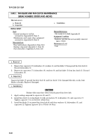
Remove four capscrews (2), lockwashers (3), washers (4), and fan blade (5) from geared fan drive hub (6).
Discard lockwashers (3).
2.
Remove six capscrews (7), lockwashers (8), washers (9), and fan blade (5) from fan clutch (1). Discard
lockwashers (8).
Inspect fan blade (5), geared fan drive hub (6), and fan clutch (1) for damaged threads, cracks, bent
blades or breaks. Replace if damaged.
CAUTION
Balance holes must face down towards geared fan drive hub.
1.
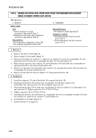
Apply sealing compound to capscrews (2) and (7).
2.
Install fan clutch (1) on fan blade (5) with six washers (9), lockwashers (8), and capscrews (7).
Tighten capscrew (7) to 13-16 lb-ft (18-22 N
•
m).
3.
Install fan blade (5) on geared fan drive hub (6) with four washers (4), lockwashers (3), and
capscrews (2). Tighten capscrew (2) to 37 lb-ft (50 N
•
m).
c. Installation
b. Inspection
a. Removal
Back to Top


