TB-9-2320-335-13-P - Page 190 of 680
TB 9-2320-335-13&P
7-10
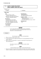
7-5.1. MASTER CYLINDER REPLACEMENT
(SERIAL NUMBERS 300000 AND ABOVE)
CAUTION
Cover or plug all open brake lines and connections immediately
after disconnection to prevent contamination. Remove all covers or
plugs prior to connecting brake lines.
NOTE
Have drainage container ready to catch brake fluid.
1.
Remove vent hose (2) from reservoir cap (3).
2.
Loosen and remove left and right front brake lines (5) from proportioning valve (9) and
master cylinder (4).
3.
Remove capscrew (8), lockwasher (7), washer (6), and bracket (10) from bracket (13).
Discard lockwasher (7).
CAUTION
Do not lean on master cylinder or damage to master cylinder
may occur.
NOTE
O-ring may fall when master cylinder is removed from hydro-booster.
4.
Remove two locknuts (11), washers (12), two locknuts (14), bracket (13), O-ring (16), splash shield
bracket (1), and master cylinder (4) from hydro-booster (15). Discard locknuts (11) and O-ring (16).
a. Removal
This task covers:
a. Removal
b. Installation
INITIAL SETUP:
Tools
General mechanic’s tool kit:
automotive (Appendix B, Item 1)
Maintenance and repair shop equipment:
automotive (Appendix B, Item 2)
Materials/Parts
O-ring (Appendix A, Item 228.6)
Lockwasher (Appendix A, Item 144)
Two locknuts (Appendix A, Item 106)
Two locknuts (Appendix A, Item 132.1)
Personnel Required
One mechanic
One assistant
Manual References
TM 9-2320-387-24-1
TB 9-2320-335-13&P, Appendix E
Equipment Condition
• Battery ground cables disconnected
(TM 9-2320-387-24-1).
• Left splash shield removed (para. 10-23.1).
Maintenance Level
Unit
Back to Top


