TB-9-2320-335-13-P - Page 204 of 680
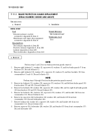
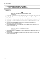
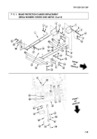
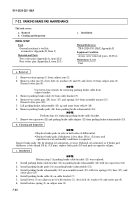
This task covers:
a. Differential Valve Removal
c. Proportioning Valve Removal
b. Differential Valve Installation
d. Proportioning Valve Installation
INITIAL SETUP:
)
TB 9-2320-335-13&P
7-24
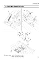
7-10. PROPORTIONING VALVE AND DIFFERENTIAL VALVE REPLACEMENT
CAUTION
• Cover or plug all open lines and connections immediately after
disconnection to prevent contamination. Remove all covers or
plugs prior to connection.
• Do not attempt to disassemble proportioning valve. Damage to
equipment will result.
NOTE
Have drainage container ready to catch brake fluid.
1.
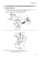
Disconnect electrical connector (2) from differential valve (4).
2.
Disconnect two brake lines (3) from differential valve (4).
3.
Disconnect two brake lines (5) from differential valve (4).
4.
Remove locknut (6), washer (7), and differential valve (4) with differential valve bracket (8) from
hydro-boost (1). Discard locknut (6).
1.
Install differential valve (4) and differential valve bracket (8) on hydro-boost (1) with washer (7) and
locknut (6). Tighten locknut (6) to 22 lb-ft (30 N
•
m).
2.
Connect two brake lines (5) to bottom of differential valve (4).
3.
Connect two brake lines (3) to top of differential valve (4).
4.
Apply lubricating oil to pins (9) of differential valve (4).
5.
Connect electrical connector (2) to differential valve (4).
1.
Disconnect two brake lines (17) from proportioning valve (16).
2.
Disconnect two brake lines (15) from proportioning valve (16).
3.
Remove locknut (14), washer (13), screw (11), and proportioning valve (16) with proportioning valve
bracket (12) from bracket (10). Discard locknut (14).
c. Proportioning Valve Removal
b. Differential Valve Installation
a. Differential Valve Removal
Tools
General mechanic’s tool kit:
automotive (Appendix B, Item 1)
Maintenance and repair shop equipment:
automotive (Appendix B, Item 2)
Materials/Parts
Locknut (Appendix A, Item 78)
Locknut (Appendix A, Item 106)
Lubricating oil (Appendix C, Item 46)
Manual References
TM 9-2320-387-10
TM 9-2320-387-24-1
TM 9-2320-387-24P
Equipment Condition
• Battery ground cables disconnected
(TM 9-2320-387-24-1).
• Hood raised and secured (TM 9-2320-387-10).
Maintenance Level
Unit
Back to Top


