TB-9-2350-368-25 - Page 77 of 120
TB 9-2350-368-25
4-5
NOTE
See Figure 4-8 for partial guide and check list of items to be
connected.
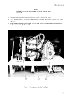
3. Place powerplant assembly (4) on powerplant test stand (5). Have helper assist.
4. Check that powerplant (4) is position within transmission brackets (6) (Figures 2-6 and 2-7) and firmly
supported.
5. Secure engine front mount to powerplant test stand front mount (7) (Figure 2-6) with two screws, four
washers, and two nuts. See Figure 4-2.
Figure 4-2. Powerplant Installed on Test Stand
Back to Top


