TB-9-2350-368-25 - Page 80 of 120
TB 9-2350-368-25
4-8
12. Connect generator ground lead and starter ground lead to ground bolt (15) on front engine mount with
wingnut and lockwasher.
NOTE
Tachometer is not necessary when using STE-ICE. If tachometer is
needed, a hand held tachometer is better suited for making
adjustments. Only the M113A3 FOV powerplant is wired with STE-
ICE transducers and harness connected on the engine.
13. Install tachometer cable on engine tachometer adapter and connect to tachometer.
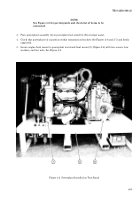
Figure 4-5. Ground Bolt
14. Connect alternator, accessory, starter, and transmission cables to powerplant test stand cables. Ensure
that connections are for M113A3/M548A3 only.
15. Connect STE/ICE harness to instrument panel/box (M548A3 must connect STE/ICE and transducers to
powerplant) and make connections to engine components, shunt, and batteries. Refer to TM 9-2350-277-
20.
16. Connect engine fuel line quick disconnect halves to powerplant test stand quick disconnect halves.
Back to Top


