TB-9-3950-253-13-P
PALLETIZED LOAD SYSTEM TRUCK, M1075 and M1075A1 (PLS) AND HEAVY EXPANDED MOBILITY TACTICAL TRUCK, M1120, M1120A2, AND M1120A4 (HEMTT), ENHANCED CONTAINER HANDLING UNIT (E-CHU)
TECHNICAL BULLETIN; OPERATOR AND FIELD MAINTENANCE, INSTALLATION INSTRUCTIONS, AND REPAIR PARTS AND SPECIAL TOOLS LIST
JULY 2009
TB-9-3950-253-13-P - Page 228 of 704
TB 9-3950-253-13&P
Change 1
0021-4
0021
HEMTT STOWAGE ASSEMBLY REMOVAL – CONTINUED
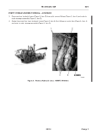
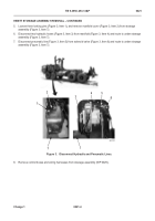
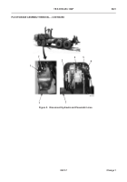
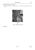
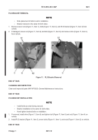
5. Loosen three locking pins (Figure 3, Item 1), and remove manifold cover (Figure 3, Item 2) from stowage
assembly (Figure 3, Item 7).
6. Disconnect two hydraulic hoses (Figure 3, Item 3) from manifold (Figure 3, Item 4) and route to under stowage
assembly (Figure 3, Item 7).
7. Disconnect pneumatic line (Figure 3, Item 5) from solenoid valve (Figure 3, Item 6) and route to under stowage
assembly (Figure 3, Item 7).
Figure 3.
Disconnect Hydraulic and Pneumatic Lines.
0021
8. Remove control boxes and wiring harnesses from stowage assembly (WP 0029).
3
1
2
5
6
7
4
7
Back to Top


