TB-9-3950-253-13-P
PALLETIZED LOAD SYSTEM TRUCK, M1075 and M1075A1 (PLS) AND HEAVY EXPANDED MOBILITY TACTICAL TRUCK, M1120, M1120A2, AND M1120A4 (HEMTT), ENHANCED CONTAINER HANDLING UNIT (E-CHU)
TECHNICAL BULLETIN; OPERATOR AND FIELD MAINTENANCE, INSTALLATION INSTRUCTIONS, AND REPAIR PARTS AND SPECIAL TOOLS LIST
JULY 2009
TB-9-3950-253-13-P - Page 415 of 704
0043-5
TB 9-3950-253-13&P
0043
INSTALLATION – CONTINUED
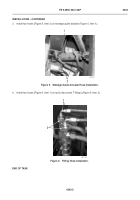
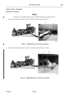
3. Install two hoses (Figure 5, Item 2) on stowage guide actuator (Figure 5, Item 1).
Figure 5.
Stowage Guide Actuator Hose Installation.
043
4. Install two hoses (Figure 6, Item 1) on quick disconnect T-fittings (Figure 6, Item 2).
Figure 6.
Fitting Hose Installation.
043
END OF TASK
467-231
1
2
467-139
1
2
Back to Top


