TM-10-4930-247-13-P - Page 25 of 309
TM 10-4930-247-13&P
Section III.
PRINCIPLES OF OPERATION
1-12.
SYSTEM TECHNICAL PRINCIPLES OF OPERATION.
a.
General.
The HEMTT Tanker Aircraft Refueling System (HTARS) described in this manual is configured for the
maximum number of refueling points.
Your mission and operating requirements will determine how many of the
system components must be connected and in what configuration.
The type of fuel nozzle used at each refueling
point will be determined by the type of aircraft being refueled.
b.
Fuel Distribution and Control.
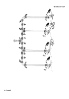
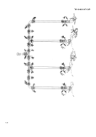
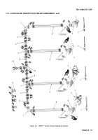
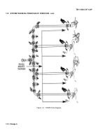
(Refer to figure 1-2) Fuel required to operate the HTARS is supplied by the HEMTT
tanker and distributed through the 3-inch supply hose to the network of 2-inch hoses, tees and elbows that make
up the four refueling points.
Fuel flow through the system is controlled by opening or closing the valves located
on each hose and tee coupling.
In the event of a fuel leak, the defective component can be isolated by closing
the nearest upstream and downstream coupling valves.
Once isolated, the defective component can be replaced
without interrupting fuel flow through the remaining refueling points.
c.
DELETED
d.
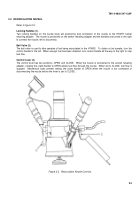
Closed Circuit Refueling (CCR) Nozzle.
The CCR nozzle is a hand operated refueling nozzle that controls system
fuel pressure to prevent over filling and over-pressurizing of the aircraft fuel system.
The vehicle adapter on the
outlet end of the nozzle contains an orifice sized to provide a predetermined fuel flow rate.
The CCR nozzle is operated manually by moving the control handle to CLOSE or OPEN position.
When set to
CLOSE, an internal poppet is seated, shutting off fuel flow.
Fuel flow is initiated by setting the control handle to
the OPEN position.
This unlocks the internal valve poppet and diaphragm allowing the fuel regulator to start fuel
flow.
Fuel supply pressure exerts a force on an internal diaphragm assembly.
This force is balanced by a
calibrated regulator spring to maintain a valve opening which provides a nominal discharge flow of 15 to 125 psig.
A flow indicator, located on the back of the nozzle housing, provides a visual indication that the nozzle valve is
closed.
When the refueled tank is full, the pressure difference at the nozzle outlet is reduced to zero, fuel flow
ceases and the red indicator will extend.
Before removal from the aircraft, the nozzle handle should be returned
to the CLOSE position.
The nozzle is disconnected from the aircraft by pulling back on the nozzle collar.
If, in an
emergency situation, the nozzle is not returned to the closed position before removal, the dry quick disconnect
action of the nozzle will close an internal valve and automatically cut off fuel flow.
When operated with the open
port or recirculation nozzles, the CCR nozzle regulates fuel pressure to 15 psi.
For additional information on the CCR nozzle, refer to TM10-4930-248-13&P.
1-8
Change 6
Back to Top

