TM-3-1040-279-12-P - Page 124 of 389
TM 3-1040-279-12&P
4-11 COVER ASSEMBLY (CONT).
p. Pump Motor Assembly.
REMOVAL
1.
2.
3.
4.
5.
6.
7.
8.
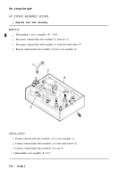
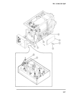
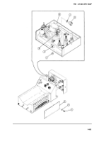
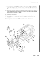
Disassemble cover assembly (P. 4-36).
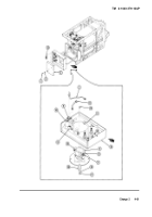
Remove two screws (1) and washers (2) and remove motor cover (3).
Disconnect fuel supply tube assembly (4) from fuel inlet adapter (5) on fuel pump
assembly (6).
Disconnect and remove pump return tube assembly (7) from elbow (8) on fuel pump assembly
(6) and cross (9) on solenoid valve (10).
Disconnect and remove solenoid inlet tube assembly (11) from elbow (12) on pump assembly
(6) and tee (13) on solenoid valve (10).
Remove electrical connections of pump assembly (6) from terminal board (14).
Remove four screws (15), washers (16), nuts (17) and cover mounting bracket (18).
Remove pump assembly (6) from cover assembly (19).
INSTALLATION
1.
2.
3.
4.
5.
6.
7.
Position pump assembly (6) in cover assembly (19) and secure with four screws (15), washers
(16), nuts (17), and cover mounting bracket (18).
Attach electrical connections from pump assembly (6) to terminal board (14). (See smoke
generator wiring (P. 4-34). Coat terminal board screw threads with sealing compound (Item
11A, App E) before securing connections.
Connect solenoid inlet tube assembly (11) between elbow (12) on pump assembly (6) and tee
(13) on solenoid valve (10).
Connect pump return tube assembly (7) between elbow (8) on fuel pump assembly (6) and
cross (9) on solenoid valve (10).
Connect fuel supply tube assembly (4) to fuel inlet adapter (5) on fuel pump assembly (6).
Position motor cover (3) on cover assembly (19) and secure with two screws (1) and washers
(2).
Adjust fuel pump pressure (P. 4-62).
4-60
Change 2
Back to Top

