TM-5-2330-325-13-P - Page 24 of 648
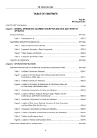
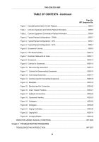
TABLE OF CONTENTS
Page No.
WP Sequence No.
HOW TO USE THIS MANUAL.
..............................................................................................................................
xvi
Chapter 1 - GENERAL INFORMATION, EQUIPMENT DESCRIPTION AND DATA, AND THEORY OF
OPERATION
General Information.
..........................................................................................................................
WP 0001
Table 1.
Abbreviations List.
.......................................................................................................
0001-2
EQUIPMENT DESCRIPTION AND DATA.
........................................................................................
WP 0002
Table 1. Major Components of Gooseneck.
..............................................................................
0002-2
Table 2. Equipment Description - Major Components.
..............................................................
0002-3
Figure 1. Plates, Decals, and Stencils.
.......................................................................................
0002-4
Table 3. Equipment Specification Table.
...................................................................................
0002-5
THEORY OF OPERATION.
...............................................................................................................
WP 0003
Chapter 2 - OPERATOR INSTRUCTIONS
DESCRIPTION AND USE OF OPERATOR’S CONTROLS AND INDICATORS.
.............................
WP 0004
Table 1. Air Brake Controls and Indicators.
...............................................................................
0004-1
Figure 1. Location of Air Tank Dump Valve Release Cable and Anti-lock
Brake System (ABS) Light.
..........................................................................................
0004-1
Table 2. Air Brake Controls and Indicators.
...............................................................................
0004-2
Figure 2. Location of Air Supply, Air Reservoirs, Air Tank Dump Valve, and
Air Tank Dump Valve Release Cable.
.........................................................................
0004-2
Table 3. Gooseneck Components, Controls, and Indicators.
....................................................
0004-3
Figure 3. Location of Kingpin, Hydraulic Pressure Gage, Platform Lift Arm
Control Lever, and Tilt Arm Control Lever.
..................................................................
0004-3
Table 4. Gooseneck Components, Controls, and Indicators.
....................................................
0004-4
Figure 4. Location of Shim Lever, Electrical Connector, Air Line Connectors,
and Neck Base Slide Bar Rod Lock.
...........................................................................
0004-4
Table 5. Gooseneck Components, Controls, and Indicators.
....................................................
0004-5
Figure 5. Location of Hydraulic and Electrical Connectors, and Gladhands.
..............................
0004-5
Table 6. Tiedown and Accessory Items.
....................................................................................
0004-6
Figure 6. Location of Tiedown and Accessory Items.
.................................................................
0004-6
OPERATION UNDER USUAL CONDITIONS.
...................................................................................
WP 0005
TM 5-2330-325-13&P
ii
Back to Top

