TM-5-2330-325-13-P - Page 322 of 648
REMOVAL
NOTE
There are front and middle spring brake control valves. Step 1 applies to the front valve.
Step 2 applies to the middle valve. Steps 3 through 5 apply to both valves.
1.
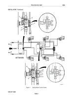
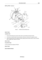
For front spring brake control valve (Figure 1, Item 7), disconnect six air lines from two tees
(Figure 1, Item 1) and fittings (Figure 1, Item 2).
2.
For middle spring brake control valve (Figure 1, Item 5), tag and disconnect seven air lines from tee
(Figure 1, Item 4), four fittings (Figure 1, Item 3), and elbow (Figure 1, Item 6).
3.
Remove spring brake control valve (Figure 1, Item 5 or 7) from air reservoir.
4.
Remove tees (Figure 1, Item 1 or 4), fittings (Figure 1, Item 2 or 3), and elbow (Figure 1, Item 6) from spring
brake control valve (Figure 1, Item 5 or 7).
5.
Install plugs or tape closed all line openings to prevent dirt contamination of system.
END OF TASK
INSTALLATION
NOTE
There are front and middle spring brake control valves. Steps 1 through 3 apply to both
valves. Step 4 applies to the middle valve. Step 5 applies to the front valve.
1.
Remove plugs or tape from air line openings.
2.
Apply antiseizing tape to threads of fittings (Figure 1, Item 2 or 3), tees (Figure 1, Item 1 or 4), and elbow
(Figure 1, Item 6) and install on spring brake control valve (Figure 1, Item 5 or 7).
3.
Apply antiseizing tape to threads of spring brake control valve (Figure 1, Item 5 or 7) and install
on air reservoir.
4.
Connect air lines to elbow (Figure 1, Item 6), four fittings (Figure 1, Item 3), and tee (Figure 1, Item 4) for
middle spring brake control valve (Figure 1, Item 5).
5.
Connect air lines to two fittings (Figure 1, Item 2) and tees (Figure 1, Item 1) for front spring brake control
valve (Figure 1, Item 7).
TM 5-2330-325-13&P
0068
0068-2
Back to Top


