TM-5-2330-325-13-P - Page 333 of 648
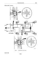
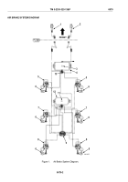
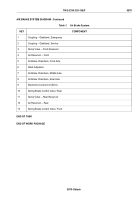
AIR BRAKE SYSTEM DIAGRAM - Continued
Table 1.
Air Brake System.
KEY
COMPONENT
1
Coupling – Gladhand, Emergency
2
Coupling – Gladhand, Service
3
Dump Valve – Front Reservoir
4
Air Reservoir – Front
5
Air Brake Chambers, Front Axle
6
Slack Adjusters
7
Air Brake Chambers, Middle Axle
8
Air Brake Chambers, Rear Axle
9
Electronic Control Unit (ECU)
10
Spring Brake Control Valve, Rear
11
Dump Valve – Rear Reservoir
12
Air Reservoir – Rear
13
Spring Brake Control Valve, Front
END OF TASK
END OF WORK PACKAGE
TM 5-2330-325-13&P
0070
0070-3/blank
Back to Top

