TM-5-2350-262-20-1 - Page 347 of 776
TM 5-2350-262-20-1
Change 3
3-337
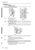
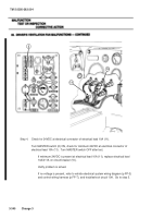
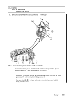
Step 4.
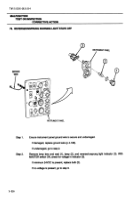
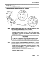
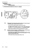
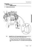
Disconnect leads (11) and (12) from heater switch (8).
Check for voltage at contact 2 (13) and
contact 1 (14) of heater switch (8), while alternately moving heater switch (8) to HIGH and LOW
positions.
If minimum 24 VDC is present at contact 2 (13) and 1 (14) of heater switch (8), repair
electrical leads (11) or (12), (p 3-1) of control wiring harness, verify problem is solved.
If no voltage is present at contacts 2 (13) and 1 (14) of heater switch (8), go to step 5.
11
13
12
8
14
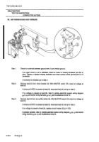
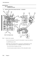
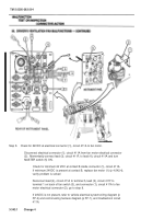
Step 5.
Disconnect lead (15) from contact 3 (16) of the heater switch (8).
Check for voltage at lead
(15).
If minimum 24 VDC is present at lead (15), replace heater switch (8) (p 4-106), verify problem
is solved.
If no voltage is present at lead (15), refer to vehicle electrical wiring schematic (p FP-3) and
control wiring harness schematic (p FP-7), and troubleshoot circuit 400.
15
8
16
82.
HEATER MOTOR INOPERATIVE
- CONTINUED
Back to Top

