TM-5-2350-262-20-1 - Page 355 of 776
TM 5-2350-262-20-1
3-343.1
Change 4
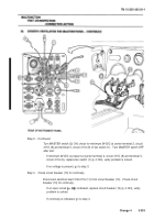
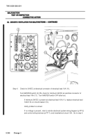
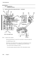
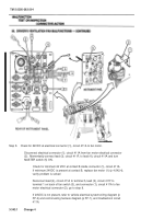
Step 8.
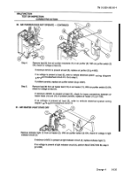
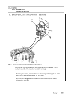
Check for 24VDC at electrical connector (1), circuit 411A to fan motor.
Disconnect electrical connector (1), circuit 411A from fan motor electrical connector
(2).
Momentarily connect lead (3), circuit 411F, to lead (4), circuit 411A and turn
MASTER switch (5) ON.
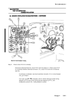
Check for minimum 24 VDC at contact B inside connector (1), circuit 411A.
If minimum 24VDC is present at contact B, replace fan motor (1) (p 4-242.4),
verify problem is solved
Reconnect lead (4), circuit 411A to terminal 5, lead (3), circuit 411F to
terminal 1 on back of fan switch (3), and connector (1), circuit 411A to fan
motor electrical connector (2), go to step 9.
If 24VDC is not present, refer to vehicle electrical system wiring diagram (p
FP-3) and control wiring harness diagram (p FP-7), and troubleshoot circuit
411A.
MASTER
SWITCH
Back to Top

