TM-5-2350-262-20-1 - Page 350 of 776
TM 5-2350-262-20-1
Change 4
3-339
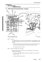
Step 2. - Continued
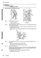
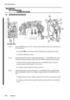
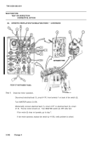
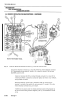
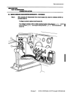
Turn MASTER switch (2) ON, check for minimum 24VDC at center terminal 2, circuit
411D (8) and terminal 5, circuit 411A (9) of fan switch (1).
Turn MASTER switch OFF
after test.
If minimum 24VDC is present at center terminal 2, circuit 411D (8) and terminal 5,
circuit 411A (9), replace fan switch (1) (p 4-106), verify problem is solved.
If no voltage is present, go to step 3.
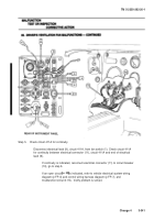
Step 3.
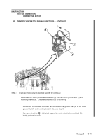
Check circuit breaker (10) for continuity.
Disconnect electrical lead 10A/411A (11) from circuit breaker (10).
Check circuit
breaker (10) for continuity.
If an open circuit
is indicated, replace circuit breaker (10) (p 4-123), verify
problem is solved.
If continuity is indicated, go to step 4.
MASTER
SWITCH
Back to Top

