TM-5-2350-262-20-3 - Page 13 of 319
ii
TM 5-2350-262-20-3
HOW TO USE THIS MANUAL
This manual describes hydraulic troubleshooting test procedures for the M9, Armored Combat
Earthmover (ACE).
Before performing any work on the M9, you should become thoroughly familiar with this
manual, its content, organization, and features.
ABOUT YOUR MANUAL
a.
Spend some time looking through this manual.
You’ll find that it has an new look, different than
most of the TMs you’ve been using.
New features added to improve the convenience of this
manual and increase your efficiency are:
1.
Accessing Information -
Extensive troubleshooting guides for specific systems lead
directly to step by step directions for problem solving and troubleshooting tasks.
2.
Illustrations
-
A variety of methods are used to make locating and fixing components much
easier.
Locator illustrations with keyed text, exploded views, and cutaway diagrams make
the information in this manual easier to understand.
3.
Keying Text With Illustrations
- Instructions are located together with figures that illustrate
the specific task you are working on.
In most cases, the task steps are located after the
figures making part identification and procedure sequence easier to follow.
The TM is the fundamental means by which the Army communicates to soldiers the requirements
and procedures necessary to perform hydraulic troubleshooting.
b.
General Features.
Your TM is the best source available for providing information and data critical
to vehicle hydraulic troubleshooting:
•
Safety summary (warning page a through c)
•
General information and equipment descriptions (chapter 1)
•
Principles of operation (chapter 2, section I)
•
Troubleshooting (chapter 3, section II)
•
Special Tools, TMDE, and Support Equipment (appendix B)
•
Special Tools, Hydraulic Troubleshooting Parts Kit, 5705562 (appendix C)
•
Torque Value Guide for Hydraulic Fittings (appendix D)
•
Schematic Diagram (appendix E)
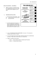
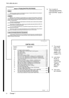
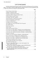
A typical example of how to use this manual is provided on the following pages.
Back to Top

