TM-5-2350-262-20-3 - Page 24 of 319
2-1
TM 5-2350-262-20-3
CHAPTER 2
HYDRAULIC SYSTEM
Section I. PRINCIPLES OF OPERATION
This section contains information relative to the principles of hydraulic system operation for the M9, Armored
Combat Earthmover (ACE). The general functional description of the vehicle and separate systems are contained
in TM 5-2350-262-20-1. Unit maintenance personnel should be familiar with the principles of operation of these
systems before working on or troubleshooting hydraulic systems. A more thorough understanding of the hydraulic
system and electrical system can be obtained by referring to the vehicle wiring diagram in TM 5-2350-262-20-1
and the vehicle hydraulic schematic in appendix E of this manual.
HYDRAULIC SYSTEM
NOTE
Refer to the vehicle hydraulic schematic, appendix E.
The hydraulic system provides hydraulic pressure to energize the suspension system, operate the winch,
ejector and apron cylinders, and bilge pump. Some hydraulic components are briefly described below.
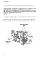
HYDRAULIC RETURN LINE FILTER
This filter, located on top of the engine, filters out contaminants from the
hydraulic oil returning to the hydraulic reservoir.
MAIN HYDRAULIC ACCUMULATOR
The main hydraulic accumulator is located on the left side of the filter
support. It is charged with nitrogen to 1,750-1,850 psi (12,066-12,756 kPa) at 70
F (21
C) and provides
immediate response to temporary needs of the SPRUNG mode that the compensating pump cannot meet. A
charge and gauge assembly is mounted on the accumulator and is used to check accumulator charge status and
to charge the accumulator.
SCOPE
Back to Top

