TM-5-2350-377-13-P - Page 211 of 404
INSTALLATION (LEFT SIDE)
NOTE
•
Installation procedures for right side manifold, reference TM 5-2350-262-20, Hydraulic
Intermediate Manifolds and Fittings Replacement, Installation (Right Side). Procedures
below are for left side only.
•
Class III leaks can occur if hydraulic lines and fittings are improperly installed or not fully
serviceable. Refer to TM 5-2350-262-20, when replacing or repairing hydraulic system
components. Always inspect system lines, fittings, and packings for serviceability before
installation.
•
Do not tighten fittings until alignment with tube is checked.
•
Use two wrenches when connecting hydraulic lines to fittings.
•
Apply lubricating oil to packings prior to installation.
1.
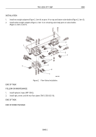
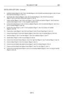
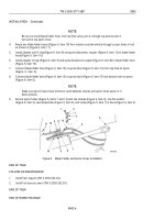
Install five new O-rings (Figure 4, Item 9) on five adapters (Figure 4, Item 8) and install adapters on bottom of
manifold (Figure 4, Item 2).
2.
Install three new O-rings (Figure 4, Item 1) on two adapters (Figure 4, Item 10) and fitting (Figure 4, Item 12)
and install adapters (Figure 4, Item 10), fitting (Figure 4, Item 12), and tee (Figure 4, Item 11) on rear of manifold
(Figure 4, Item 2).
3.
Install five new O-rings (Figure 4, Item 5) on four adapters (Figure 4, Item 7) and elbow (Figure 4, Item 6), and
install adapters (Figure 4, Item 7) and elbow (Figure 4, Item 6) on front of manifold.
4.
Install seven new O-rings (Figure 4, Item 4) on seven adapters (Figure 4, Item 3) and install adapters on top
of manifold (Figure 4, Item 2).
M0061HBF
1
2
3
6
7
8
9
1
10
1
10
11
12
4
2
5
FRONT
VIEW
REAR
VIEW
Figure 4.
Manifold Tubes Installation.
TM 5-2350-377-13&P
0041
0041-5
Back to Top

