TM-5-2350-377-13-P - Page 206 of 404
INSTALLATION
1.
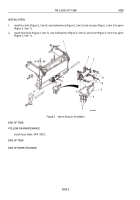
Install two straight adapters (Figure 2, Item 4) on ports 1A on top and bottom valve bodies (Figure 2, Item 3).
2.
Install twelve straight adapters (Figure 2, Item 1) on remaining valve body ports on valve bodies
(Figure 2, Items 2 and 3).
M0057HBF
3
3
4
4
1
1
1
1
1
1
1
2
2
Figure 2.
Flow Valves Installation.
END OF TASK
FOLLOW-ON MAINTENANCE
1.
Install hydraulic hoses (WP
0042).
2.
Install right, center, and left rear floor plates (TM 5-2350-262-10).
END OF TASK
END OF WORK PACKAGE
TM 5-2350-377-13&P
0040
0040-2
Back to Top


