TM-5-2350-377-14-P - Page 210 of 335
TM 5-2350-377-14&P
TRACK & BLADE CONTROL BOX REPAIR
DISASSEMBLY
NOTE
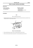
Steps 1 through 3 apply to Figure 97.
1. Slide track and blade control box (item 2) behind instrument panel (item 6) and remove two screws (item
4) and
flat washers (item 5) on instrument panel ( item 6).
Figure 97.
Control Box Assembly.
2. Remove manifold harness connector
(item 3) from track and blade control box (item 2).
3. Remove control box power harness connector (item 1) from track and blade control box (item
2).
0037 00-1
0037 00
INITIAL SETUP
Tools/Test Equipment
Tool kit, general mechanic's
(Item 6, WP 0056 00)
Equipment Conditions
Front of vehicle blocked
(TM 5-2350-262-20-1)
Hydraulic system pressure relieved
(TM 5-2350-262-20-1)
Back to Top


