TM-5-2350-378-23-P - Page 343 of 644
APPARENT HYDRAULIC DIAGNOSTIC CENTER (HDC) SYSTEM PROBLEM - Continued
CONDITION/INDICATION
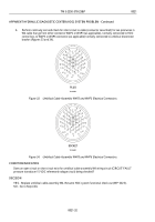
Does an open circuit or short circuit exist in cable assembly W2 or W3 wiring circuit (CIRCUIT FAULT pressure
transducer 15 VDC reference circuit) being checked? (Refer to FP-23 through FP26, for wiring schematic
diagrams of electrical cable assemblies W2 and W3).
DECISION
YES - Replace embedded cable assembly (W2 or W3, as applicable) associated with designated "CIRCUIT
FAULT" pressure transducer 15 VDC reference voltage circuit wiring.
NO - Go to Step (39).
STEP
39.
Check if cable assembly W4 has an open or shorted circuit.
a.
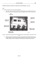
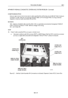
Disconnect umbilical cable W4 connector W4P2 on W4P3 (Figure 32) (from HDC control box connector
J2 or J3, as applicable) associated with designated "CIRCUIT FAULT" pressure transducer.
CONTROL BOX
CONNECTOR J3
UMBILICAL CABLE
CONNECTOR W4P1
UMBILICAL CABLE
CONNECTOR W4P2
HDC
CONTROL BOX
T01932HDC
CONTROL BOX
CONNECTOR J1
UMBILICAL CABLE
CONNECTOR W4P3
CONTROL BOX
CONNECTOR J2
Figure 32.
Umbilical Cable Assembly W4 Connections to Hydraulic Diagnostic Center (HDC) Control Box.
TM 5-2350-378-23&P
0021
0021-31
Back to Top


