TM-5-2350-378-23-P - Page 368 of 644
Table
2.
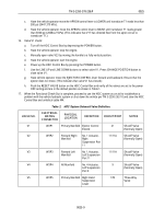
HDC System Solenoid Valve Definition - Continued.
VALVE NO.
ELECTRICAL
MATING
CONNECTOR
PHYSICAL
LOCATION
DEFINITION
CIRCUIT/PORT
NOTES
V6
W3P6
Aft Manifold
No. 4 Actuator,
Left Suspension
Port 2
2
Shutoff Valve
(Normally Open)
V7
W3P7
Aft Manifold
No. 3 Actuator,
Left Suspension
Port 2
2A/2
Shutoff Valve
(Normally Open)
V8
W3P8
Aft Manifold
No. 4 Actuator,
Left Suspension
Port 11
11
Shutoff Valve
(Normally Open)
V9
W3P9
Forward Left
Manifold
Left Bump Stop
Cylinder Extend
11/11B
Shutoff Valve
(Normally Open)
V10
W3P10
Forward Right
Manifold
Right Bump Stop
Cylinder Extend
11/11B
Shutoff Valve
(Normally Open)
V11
W2P11
Primary Manifold
Left Hand
Suspension
Lower
17L/7
Three-Way
Valve
V12
W2P12
Primary Manifold
Suspension
Relief Valve Port
9
9
Shutoff Valve
(Normally Open)
V13
W2P13
Primary Manifold
Suspension
Relief Valve,
Main
Accumulator
9A
Shutoff Valve
(Normally Open)
V14
W2P14
Primary Manifold
Winch Control
Shutoff
C2
Three-Way
Valve
V15
W2P15
Primary Manifold
Right Hand
Suspension
Raise
3R
Three-Way
Valve
V16
W2P16
Primary Manifold
Left Hand
Suspension
Raise
3L
Three-Way
Valve
V17
W2P17
Primary Manifold
Apron Cylinder
Retract (Raise)
19
Three-Way
Valve
V18
W3P18
Aft Manifold
No. 4 Actuator,
Left Suspension
Port 9 to Port 2
Shutoff Valve
(Normally Open)
TM 5-2350-378-23&P
0025
0025-10
Back to Top


