TM-5-2350-378-23-P - Page 371 of 644
M0055HDC
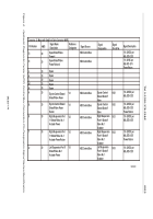
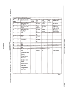
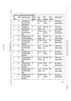
Connector J1: Mates with Umbilical Cable Connector W4P1
Connector J2: Mates with Umbilical Cable Connector W4P2
Pin Number
AWG
A
B
C
A
20
20
20
20
20
20
B
C
F
D
E
16
16
16
HDC Control Box
Power
Spare Shutoff Valve
Power 1
Spare Shutoff V
alve
Power Return 1
Spare Shutoff Valve
Power 2
Spare Shutoff Valve
Power Return 2
Spare Shutoff Valve
Power 3
Spare Shutoff Valve
Power Return 3
HDC Control Box
Power Return
Spare
Vehicle 15A
Circuit Breaker
Vehicle
Ground
Connection
HDC Control
Box
HDC Control
Box
HDC Control Box
HDC Control Box
HDC Control Box
HDC Control Box
HDC Control Box
HDC Control Box
1070
1069
18 - 32VDC
per
MIL-STD-1
275, 10A
Maximum
18 - 32VDC per
MIL-STD-1275
18 - 32VDC per
MIL-STD-1275
Power Return
18 - 32VDC per
MIL-STD-1275
18 - 32VDC per
MIL-STD-1275
Power Return
18 - 32VDC per
MIL-STD-1275
18 - 32VDC per
MIL-STD-1275
Power Return
24VDC
Ground
The maximum
current rating
includes the 4
spare transducers
and 4 valves
turned ‘ON’
simultaneously.
Signal Name
Description
Reference
Designator
Signal Source
Signal
Designation
Signal
Circuit No.
Signal
Description
Comments
Pin Number
AWG
Signal Name
Description
Reference
Designator
Signal Source
Signal
Designation
Signal
Circuit No.
Signal Description
Figure 3.
Hydraulic Diagnostic Center (HDC) Control Box Connectors-Pin Designation Signal Names/Identification.
TM 5-2350-378-23&P
0025
0025-13
Back to Top


