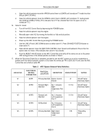
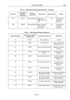
TM-5-2350-378-23-P - Page 376 of 644
M0060HDC
y
x
w
20
20
20
20
1057
Right Hand
Suspension Raise
Shutoff Valve
Right Hand
Suspension Raise
Shutoff Valve
Left Hand
Suspension Raise
Shutoff V
alve
1058
1059
1060
1061
1062
1063
1064
V16
V16
V15
V15
V17
V17
V18
V18
20
20
20
z
AA
BB
DD
20
CC
Apron Cylinder Retract
Shutoff Valve Power
Apron Cylinder Retract
Shutoff Valve Power
Return
Right Hand Suspension
Raise Shutoff Valve
Power Return
Right Hand Suspension
Raise Shutoff Valve
Power
Left Hand Suspension
Raise Shutoff Valve
Power Return
Left Hand Suspension
Raise Shutoff Valve
Power
Left Suspension Port 9
to Port 2 Shutoff Valve
No. 4 Actuator Power
Left Suspension Port 9
to Port 2 Shutoff Valve
No. 4 Actuator Power
Return
Apron Cylinder
Retract Shutoff
Valve
Apron Cylinder
Retract Shutoff
Valve
Left Hand
Suspension Raise
Shutoff Valve
Valve Left
Suspension Port
9 to Port 2
Shutoff Valve
No. 4 Actuator
Valve Left
Suspension Port
9 to Port 2
Shutoff Valve
No. 4 Actuator
HDC Control Box
HDC Control Box
HDC Control Box
HDC Control Box
HDC Control Box
HDC Control Box
HDC Control Box
HDC Control Box
18 - 32VDC per
MIL-STD-1275
Power Return
18 - 32VDC per
MIL-STD-1275
18 - 32VDC per
MIL-STD-1275
Power Return
18 - 32VDC per
MIL-STD-1275
18 - 32VDC per
MIL-STD-1275
Power Return
18 - 32VDC per
MIL-STD-1275
18 - 32VDC per
MIL-STD-1275
Power Return
18 - 32VDC per
MIL-STD-1275
Pin Number
AWG
Signal Name
Description
Reference
Designator
Signal Source
Signal
Designation
Signal
Circuit No.
Signal Description
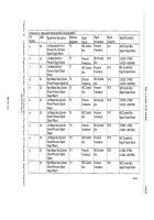
Connector J2: Mates with Umbilical Cable Connector W4P2
Figure 8.
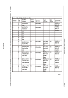
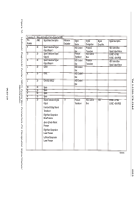
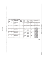
Hydraulic Diagnostic Center (HDC) Control Box Connectors-Pin Designation Signal Names/Identification.
TM 5-2350-378-23&P
0025
0025-18
Back to Top


