TM-5-2350-378-24-P - Page 340 of 790
TM 5--2350--378--24&P
0016 00--37
HYDRAULIC OIL OVERHEATS -- Continued
0016 00
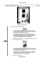
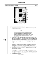
Figure 25. HDC Control Box
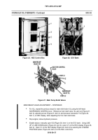
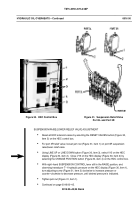
Figure 26. DCV Bank
Figure 27. Main Pump Relief Valves
MAIN RELIEF VALVE ADJUSTMENT -- CONTINUED
For 13L; repeat the previous steps for main relief valve 13L using the left--hand
SUSPENSION CONTROL lever. Reference main relief valve 13L jam nut (Figure 27,
item 3), adjusting screw (Figure 27, item 2), and pressure transducer T4 (Figure 25,
item 1) on HDC display, when adjusting the 13L main relief valve.
Stop engine; relieve hydraulic pressure.
Enable ejector; manually open V23 (Figure 26, item 1) on the DCV bank. Using LINE
UP or LINE DOWN button (Figure 25, item 3), select V1 on the HDC display (Figure 25,
item 2). Open V1 on the HDC display (Figure 25, item 2) by selecting the CHANGE
POSITION button (Figure 25, item 4) on the HDC control box.
Back to Top

