TM-5-2350-378-24-P - Page 410 of 790
TM 5--2350--378--24&P
0017 00--9
LEFT REAR CORNER DOES NOT RAISE IN SPRUNG OR UNSPRUNG MODE -- Continued
0017 00
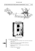
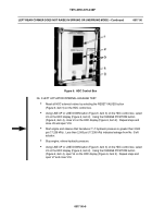
Figure 6. HDC Control Box
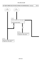
No. 3 LEFT ACTUATOR INTERNAL LEAKAGE TEST
Reset all HDC solenoid valves by selecting the RESET VALVES button
(Figure 6, item 5) on the HDC control box.
Using LINE UP or LINE DOWN button (Figure 6, item 3) on the HDC control box, select
V4 on the HDC display (Figure 6, item 2). Using the CHANGE POSITION button
(Figure 6, item 4), close V4 on the HDC display (Figure 6, item 2). Repeat steps and
close V6 and open V18.
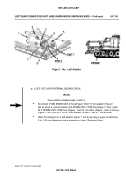
Start engine and observe that transducer T--7 hydraulic pressure is greater than 2,500
psi (17,238 kPa). Less than 2,500 psi (17,238 kPa) indicates leakage from No. 3 left
actuator.
Stop engine; relieve hydraulic pressure.
Using LINE UP or LINE DOWN button (Figure 6, item 3) on the HDC control box, select
V4 on the HDC display (Figure 6, item 2). Using the CHANGE POSITION button
(Figure 6, item 4), open V4 on the HDC display (Figure 6, item 2). Repeat steps and
open V7 and close V18.
Back to Top

