TM-5-2350-378-24-P - Page 400 of 790
TM 5--2350--378--24&P
HYDRAULIC OIL OVERHEATS -- Continued
0016 00
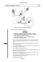
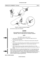
Figure 68. Actuator Accumulator Charging
ACTUATOR ACCUMULATOR CHARGING
CAUTION
Ensure regulator valve is fully backed off to relieve tension in
diaphragm. Failure to comply may result in damage to equipment.
NOTE
Have suitable container ready to catch oil.
Adjust regulator valve (Figure 68, item 2) on nitrogen tank (Figure 68, item 3) to
800--900 psi (5,516--6,206 kPa).
Open shutoff valve (Figure 68, item 4). Read pressure measuring device (Figure 68,
item 5).
When pressure reaches 800--900 psi (5,516--6,206 kPa), close shutoff valve (Figure 68,
item 4), nitrogen tank valve (Figure 68, item 1), and accumulator charge valve
(Figure 68, item 10).
Wait 15 minutes and open accumulator charge valve (Figure 68, item 10). Read
pressure measuring device (Figure 68, item 5) to determine if accumulator can retain the
charge.
Tighten nut (Figure 68, item 7) on charge valve (Figure 68, item 10). Close nitrogen tank valve
(Figure 68, item 1). Back off regulator valve (Figure 68, item 2), open bleed valve (Figure 68,
item 11), and bleed hose pressure to 0 psi. Remove adapter valve (Figure 68, item 9) from
charge valve (Figure 68, item 10). Remove pressure measuring device (Figure 68, item 5) from
bleed valve (Figure 68, item 11) on charging harness. Install charge valve cap (Figure 68,
item 8) on actuator accumulator (Figure 68, item 6).
END OF WORK PACKAGE
0016 00--97/98 blank
Back to Top

