TM-5-3805-254-14-P-2 - Page 179 of 894
BRAKES-AIR
TRUCK SERVICE MANUAL
ridge to ascertain that the water accumulation is not
related to the following listed items:
a. An outside air source has been used to charge
the system.
This air did not pass through the
drying bed.
b. Air usage exceptionally high and not normal for a
highway vehicle.
This may be due to accessory
air demands or some unusual air requirement
that does not allow the compressor to load and
unload (compressing and non-compressing
cycle) in a normal fashion.
Check for high air
system leakage.
c. The air dryer has been installed in a system that
has been previously used without an air dryer.
This type system will be saturated with moisture
and several weeks of operation may be required
to dry it out.
d. Location of the air dryer is too close to the air
compressor.
Refer to "Installation" section.
2.
Check mounting bolts for tightness.
Check all air
and electrical connections.
3.
Check the operation of the integral single check
valve in the AD-2 or the "in-line" check valve used
with AD-1.
Build the air system, to governor cutout
and observe the test air gauge installed in the
supply reservoir.
A rapid loss of pressure could
indicate a failed check valve.
This can be
confirmed by checking at the purge valve exhaust.
NOTE: Purge valve will be open when governor
cut-out pressure is reached.
Allow two minutes
for purge cycle before testing the check valve.
4.
Check for excessive leakage at the purge valve by
coating the exhaust with a soap solution while the
compressor is loaded (compressing air).
5.
Check the operation of the safety valve by pulling the
exposed stem while the compressor is loaded
(compressing air).
There must be an exhaust of air
while the stem is held and the valve should reseat
when the
stem is released.
6.
Check all lines and fittings leading to and from the air
dryer for leakage and integrity.
7.
Check the operation of the heater and thermostat
during cold weather operation.
This can be done by
allowing the end cover assembly to cool below 100 C
(500 F) and feeling the end cover when the ignition is
turned on.
The end cover should be warm to the
touch within a few moments.
Warming should cease
at about 300 C (850 F).
The desiccant change interval may vary;
however, it is generally recommended that the desiccant
be replaced every 12 months (yearly).
If experience has
shown that extended or shortened life has resulted for a
particular installation, then the yearly interval can be
increased or reduced accordingly.
REMOVAL OF DESICCANT CARTRIDGE AD-1 & AD-2
1.
Make certain the vehicle is safely parked.
Block the
wheels if necessary.
2.
Drain the air system completely being sure that the
lines leading into and out of the air dryer are at
atmospheric pressure.
3.
Disconnect the air line from the end cover and mark
location of this port on the dryer.
4.
Disconnect the heater wire.
5.
Loosen the three capscrews on the end cover and
turn the retaining clamps aside (capscrews may be
left finger tight).
6.
Locate the notch in the dryer shell.
While pushing
the end cover up into the dryer, insert the blade of a
screwdriver in the notch and slowly pry out the
retainer ring.
Remove the end cover assembly and
set it aside temporarily.
7.
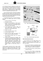
Using a 3/4" socket wrench, remove the cartridge
and desiccant sealing plate assembly.
NOTE: Be certain the desiccant sealing
plate assembly comes out with the
cartridge.
177
Back to Top

