TM-5-3805-254-14-P-2 - Page 185 of 894
BRAKES-AIR
TRUCK SERVICE MANUAL
No. 6-32 phillips head screws.
10. Lubricate and install the large diameter O-ring
around the end cover assembly.
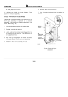
OUTLET PORT CHECK VALVE ON AD-2
The one-way check valve located in the outlet port of the
AD-2 dryer assembly is replaced as a complete
assembly.
The removal and installation procedure is as
follows (Refer to Fig.
20).
1.
Set parking brake by applying the control valve.
2.
Bleed air from main air reservoir.
3.
Locate outlet port on air dryer assembly which is the
air supply to main air reservoir.
Then disconnect the
air supply line or hose.
4.
After hose is disconnected, the elbow and check
valve assembly can then be removed separately.
5.
Install new check valve assembly and seal.
6.
Reinstall elbow and connect hose.
7.
After air supply is restored check connection for
air leaks.
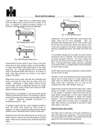
Fig. 20
Typical Air Dryer
Installation
182A
Back to Top

