TM-5-3805-254-14-P-2 - Page 415 of 894
TRUCK SERVICE MANUAL
ENGINE
Electric Connections
Secure electric connections to mounted equipment,
using wire as specified.
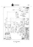
See engine wiring diagram.
Fan Installation
Note:
When installing fan to fan hub 5/16 inch [7.94 mm]
capscrew must have 15/32 inch [11.91 mm] thread
engagement, 3/8 inch [9.53 mm] capscrews must have
9/16 inch [14.29 mm] thread engagement, 1/2 inch
[12.70 mm] capscrews must have 3/4 inch [19.05 mm]
thread engagement.
Check decal on fan hub or water
pump pulley for proper thread length.
The fan may be
installed before or after engine dynamometer testing.
ENGINE TESTING
Engine
break-in
and
testing
are
accomplished
simultaneously.
Break-in on a new or rebuilt engine is
necessary because it provides an operating period
during which moving parts acquire their final finish and
mating surfaces reach a full seat.
Engine testing helps
detect possible assembly errors, need for adjustments
as engine "break-in " and establishes a period for final
adjustments for best engine performance.
Priming The Fuel System
1. Fill fuel tanks and filter(s) with clean No.
2 diesel
fuel oil meeting the specifications in Group 18.
a. With PT (type G) fuel pump, fill pump through
plug next to tachometer with clean fuel.
2. If injector and valve or other adjustments have
been disturbed, be sure they have been properly
adjusted before starting engine.
Priming The Lubricating System
Note:
If engine is equipped with a turbocharger, remove
oil inlet line and lubricate bearing with approximately 2 to
3 oz [60 cc] of clean engine lubricating oil.
Reconnect oil
inlet line.
1. Fill crankcase to "L" (low) mark on dipstick.
See
Lubricating Oil Specifications, Group 18.
Note:
Some engine dipsticks have dual markings with
high and low level marks; static oil marks on one side
and engine running at low idle speed marks on opposite
side.
Be sure to use proper scale.
2. Remove plug from head of lubricating oil filter
housing or gear case to prime system.
(See 1 or 2, Fig.
1433.)
Back to Top

