TM-5-3805-254-14-P-2 - Page 414 of 894
TRUCK SERVICE MANUAL
ENGINE
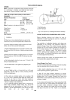
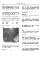
2. Loosen locknut and back off adjusting screw. Insert
feeler gauge between rocker lever and crosshead. Valve
clearances are shown in Table 14-13. Turn screw down
until lever just touches gauge and lock in this position.
Fig.14-31. Tighten locknut to 30 to 40 ft-lb. [4.1 to 5.5 kg
m] torque. When using ST-669 torque to 25 to 35 it-lb.
[3.5 to 4.8 kg mi.
3. Continue to bar engine to next "VS" mark and adjust
each cylinder in firing order. See Table 14-10. After
injector and valve adjustment is completed, bar or crank
(in chassis overhaul) engine several revolutions to
Table 14-13: Valve Clearance - Inch [mm] (Torque
Method)
Intake Valves
Exhaust Valves
Cold Set
Hot Set
Cold Set
Hot Set
Aluminum Rocker Housing
0.014
0.014
0.027
0.027
[0.36]
[0.36]
[0.69]
[0.69]
Cast Iron Rocker Housing
0.016
0.014
0.029
0.027
[0.41]
[0.36]
[0.74]
[0.69]
Back to Top

