TM-5-3805-254-14-P-2 - Page 479 of 894
TRUCK SERVICE MANUAL
FUEL SYSTEM
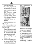
4. Screw snubber back into gauge stem.
5. Place an injector into operating position In test
stand.
Start the test stand.
When solid fuel
begins to flow from the snubber, turn gauge
upright quickly and assemble to snubber.
Let
test stand run while gauge is tightened securely
to snubber.
6. Assemble gauge to mounts secure with machine
screws and nuts.
7. Start test stand and observe gauge hand rise
from 0 to 120 psi [0 to 827 kPa].
It should take
approximately 2 to 3 seconds for hand to rise to
120 psi [827 kPa].
If gauge hand is slow to rise
and fall, carefully repeat Steps 1 through 6.
8. Check for gauge hand vibration, it should not
occur if copper line is properly routed and
adjusted.
a. Tubing must be adjusted so it is neither "pulling"
or "pushing" on the gauge.
b. Tubing on the gauge must not contact any
member of test stand such as frame, motor or
gear pump cover.
c. Contact of tubing to any member of test stand
will transmit mechanical vibration into gauge and
defeat purpose of snubbers and gauge mounts.
Changing Oil And Filter
When changing oil and filters in test stand, adjust
regulator to lowest possible pressure during pump pickup
to prevent air from being forced into gauge line.
If slow
gauge hand response does occur, it is an indication air
entered the system and the bleeding process Steps 1
through 6 must be performed.
Calibrating The ST790 Test Stand
1. Before operating the test stand make sure that
the cam box is filled to the top level of the sight
glass with clean SAE 30 nonfoaming lubricating
oil.
2. Fill the hydraulic fluid reservoir to bulb level with
clean Type A automatic transmission fluid.
Be
careful not to allow oil to enter the standpipe in
the center of the reservoir.
3. The test oil tank on the stand must be kept at
least 3/4 full of Cummins 9901168 test oil or
Mobil Oil Company No. MCL41.
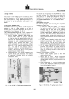
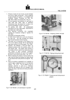
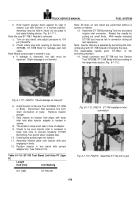
4. Align timing mark (Fig.
6171) and open the
hydraulic valve.
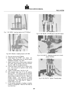
Place the load cell, ST7905111,
in the test stand and clamp in place by opening
the air valve.
Fig.
6181.
Note:
Never operate test stand with load cell in position.
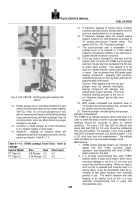
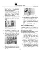
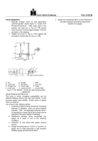
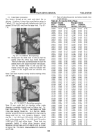
5. Adjust air pressure by turning the knurled button
on the air regulator until the load cell indicates
within marked band on load cell gauge.
Lock the
knurled button in place with the locknut.
Note
the air gauge pressure (gauge at top of Hydraulic
Reservoir).
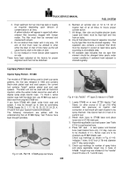
Fig.
6182.
Load cell should read
between 370 and 390 when adjusted within
marked band on dial.
Back to Top

