TM-5-3805-254-14-P-2 - Page 522 of 894
TRUCK SERVICE MANUAL
Tachometer Cable
The tachometer drive is a standard SAE size operating
at 1/2 engine speed.
Fill cavity with clean, heavy grease
before attaching cable.
Do not force tang into slot.
If fit
is incorrect, change tang to a new, standard SAE type.
When tachometer cable outer casing is plastic, do not
route near exhaust manifold or other "hot" areas.
Fuel Pump Throttle Travel
The most sensitive adjustment on units using a hydraulic
governor is fuel pump throttle travel.
Do not change the
idle throttle stop screw setting (front).
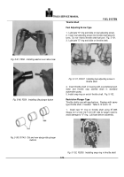
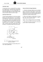
Using a protractor
or ST-1162, Fig.
5-126, set the fuel pump lever idle
position centerline at 55 deg.
from vertical on centerline
of fuel pump throttle shaft.
Lock throttle lever screw.
Set
the centerline of the fuel pump lever in the maximum
position at 27 deg.
from vertical.
Lock rear adjusting
screw.
Recheck throttle lever centerline travel, it must
be 28 deg., or as specified, between idle and full throttle.
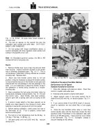
Fig.
5-126, F-5187.ST-1162 fuel pump throttle
adjustment template
For PT Fuel Pump calibration and speed setting refer to
FUEL PUMP CALIBRATION.
Governor Shaft And Linkage Adjustment
1.
Governor-to-fuel-pump linkage must be connected
with both fuel pump throttle and governor terminal shaft
levers in fuel shut-off or Idle position.
The fuel pump
throttle lever will be all the way down against stop (full
clockwise) and the governor terminal shaft away from the
engine will be in extreme clockwise position.
2.
Adjust control linkage to a length (about 9-1/2 inches
[241 mm] ) which will permit installation of unibals in
levers without any movement of levers.
Caution:
Be sure linkage and levers are not binding.
3.
Start engine and adjust low speed stop screw (atop
governor head) for desired idling speed.
517
FUEL SYSTEM
Back to Top

