TM-5-3805-254-14-P-2 - Page 626 of 894
TRUCK SERVICE MANUAL
SPRINGS
Legend for Fig.
13
Key
Description
Key
Description
Key
Description
19
WASHER, Lock
37
SLIDE, Top, Pad
20
NUT
38
BUSHING, Spring Eye
21
SCREW, Set
39
LUBRICATOR, Spring, Pin
22
BOLT, Spring, Center
40
PIN, Spring, Front
23
SPRING, Assembly
41
BOLT
24
CAP, Retainer, Saddle
42
ADAPTER, Beam End
25
RIVET, Bracket Mtg
43
BEAM, Equalizer
26
BRACKET/, Spring, Rear
44
TUBE, Center, Cross
27
STOP, Axle, Rear
45
BUSHING, Beam End
28
RIVET
46
SCREW, Set
11
STOP, Axle, Front
29
NUT
47
SLEEVE, Beam, Center
12
BRACKET, Spring, Frt
30
SPACER
4.8
NUT
13
NUT
31
BOLT
49
SHAFT, Torque Rod
14
WASHER, Lock
32
STUD, Saddle, Cap
50
BUSHING, Torque Rod
15
KEY, Draw, Spring
33
WASHER, Lock
51
ROD, Torque
16
CLIP, Spring
34
NUT, Top, Pad, Bolt
52
SHAFT, W/Bushing Torque
17
PAD, Top, Spring
35
NUT, Saddle, Cap Stud
Rod
18
BOLT, Top, Pad
36
SADDLE, Assembly
53
BRACKET, Torque Rod
54
BRACKET, Spring Rear
Extended Leaf Only
CAUTION
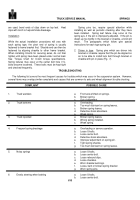
Three types of equalizer beams are utilized in the
manufacturing of International trucks equipped with
equalizer beam suspensions.
Although the appearance
of the
equalizer beams is similar, there is a substantial
difference
in
the
material
of
which
they
are
manufactured.
The materials of the equalizer beams involved are
aluminum, cast iron and nodular iron.
Aluminum and
cast iron equalizer beams are manufactured such that
they can be stressed in either direction.
Nodular iron
equalizer beams are manufactured such that they can be
stressed in one direction only.
Thus, it is imperative that
nodular
iron equalizer beams be installed with the correct side
up.
To aid in identification and facilitate installation of
nodular iron beams, an arrow and the word UP have
been molded on the side of nodular iron beams.
Also,
reinforcing gate pads have been designed into each end
and middle of the top side of nodular iron beams.
Nodular iron equalizer beams must be installed with
gate pads on top side of beam and the arrow molded on
the beam side pointing upward.
Installing Equalizer Beams and Cross Tube
1.
Place one equalizer beam in position in trunnion of
spring saddle and install bushing retainer caps and
nuts.
Tighten the nuts only until the caps fit snugly
against the bushing.
NOTE :
Do not tighten bushing retainer cap nuts to
specified torque until axles have been connected to
equalizer beams.
2.
Place cross tube seal assemblies in position on ends
of cross tube (bronzed bushed models only).
3.
Apply a light coat of chassis lubricant to the ends of
the cross tube which fit into the
beam center sleeves (bronze bushed models). On
those models having rubber bushed center sleeves,
wipe ends of cross tube clean and pack center
bushing with approximately 2 ounces of viscous
chassis lubricant.
4.
Place one end of cross tube into center sleeve of
installed equalizer beam.
Be sure tube seats into
sleeve.
5.
Assemble other equalizer beam to cross tube and
position beam in spring saddle.
Install bushing
retainer caps and nuts.
Tighten the nuts only until
the caps fit snugly against the bushings.
(See
"NOTE " above.
)
619
Back to Top


