TM-5-3805-264-13-P - Page 17 of 660
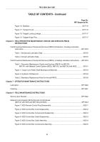
TABLE OF CONTENTS
Page No.
WP Sequence No.
How To Use This Manual.
......................................................................................................................................
xix
Chapter 1 - GENERAL INFORMATION, EQUIPMENT DESCRIPTION, AND THEORY OF
OPERATION
General Information.
..........................................................................................................................
WP 0001
Equipment Description and Data.
......................................................................................................
WP 0002
Figure 1. M917A1 and M917A2.
..................................................................................................
0002-2
Figure 2. M917A1 with MCS and M917A2 with MCS.
.................................................................
0002-2
Figure 3. Driver's Side Front of Dump Truck.
..............................................................................
0002-3
Table 1. Driver's Side Front of Dump Truck.
................................................................................
0002-3
Figure 4. Passenger's Side Rear of Dump Truck.
.......................................................................
0002-4
Table 2. Passenger's Side Rear of Dump Truck.
.........................................................................
0002-4
Table 3. Equipment Data.
............................................................................................................
0002-6
Theory of Operation.
..........................................................................................................................
WP 0003
Figure 1. Tailgate Components: M917A1 and M917A2.
..............................................................
0003-2
Figure 2. Tailgate Components: M917A1 and M917A2 with MCS.
.............................................
0003-3
Figure 3. Hydraulic System.
.........................................................................................................
0003-5
Chapter 2 - OPERATOR INSTRUCTIONS
Description and Use of Operator's Controls and Indicators.
..............................................................
WP 0004
Table 1. Console.
.........................................................................................................................
0004-1
Figure 1. Console.
.......................................................................................................................
0004-1
Table 2. Dashboard and Instrument Cluster.
...............................................................................
0004-2
Figure 2. Dashboard and Instrument Cluster.
..............................................................................
0004-2
Table 3. Hydraulics.
.....................................................................................................................
0004-3
Figure 3. Hydraulics.
....................................................................................................................
0004-3
Table 4. Cargo Cover and Transport Lock.
.................................................................................
0004-4
Figure 4. Cargo Cover and Transport Lock.
................................................................................
0004-4
Table 5. Material Control System.
...............................................................................................
0004-5
Figure 5. Material Control System.
..............................................................................................
0004-5
TM 5-3805-264-13&P
iii
Back to Top

